The ignition system on a jet unlike a car engine is only required at start-up to provide initial combustion of the fuel. Kerosene or Jet A1 in it’s atomised form usually requires a 1 joule spark to ignite and therefore some form of high energy igniter system is needed.
Jet engine ignition systems usually consist of a high energy source in the form of a pulsed capacitative discharge via high energy ignition leads and a plug. The exciter units are often no more than black boxes with a 24v DC supply and an output of 2Kv. The energy released with each spark varies with the type of engine and igniter unit but is often in the range of 3 to 12J. The peak current at each discharge can be as high as a 1000 Amps although this is only for a few microseconds.
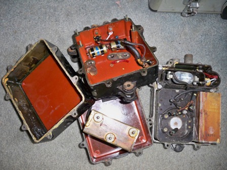
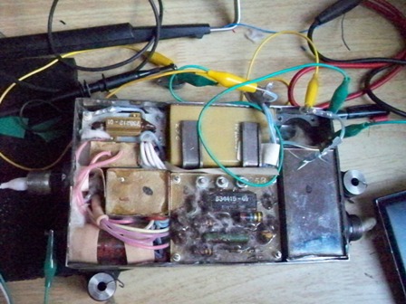
A few months ago I obtained several of these old igniter units that were in various states of condition. Most had been gutted with various components removed. The units are all fairly old dating back to 1950’s or 60’s and were probably used in aircraft such as the De Havilland Vampire or Sea Vixen.
These are very simple units that use a trembler switch to convert DC to AC. The high voltage comes from a transformer similar to a car coil that is rectified with a diode. A large capacitor charges up and discharges across a spark gap to release the high energy pulse.
I could have probably used the original components and built up a box, however I was inspired by Paul Bennett’s all semiconductor igniter unit that he designed to build one myself and install it in one of the old boxes. Here’s Paul’s igniter unit:
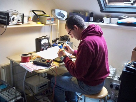
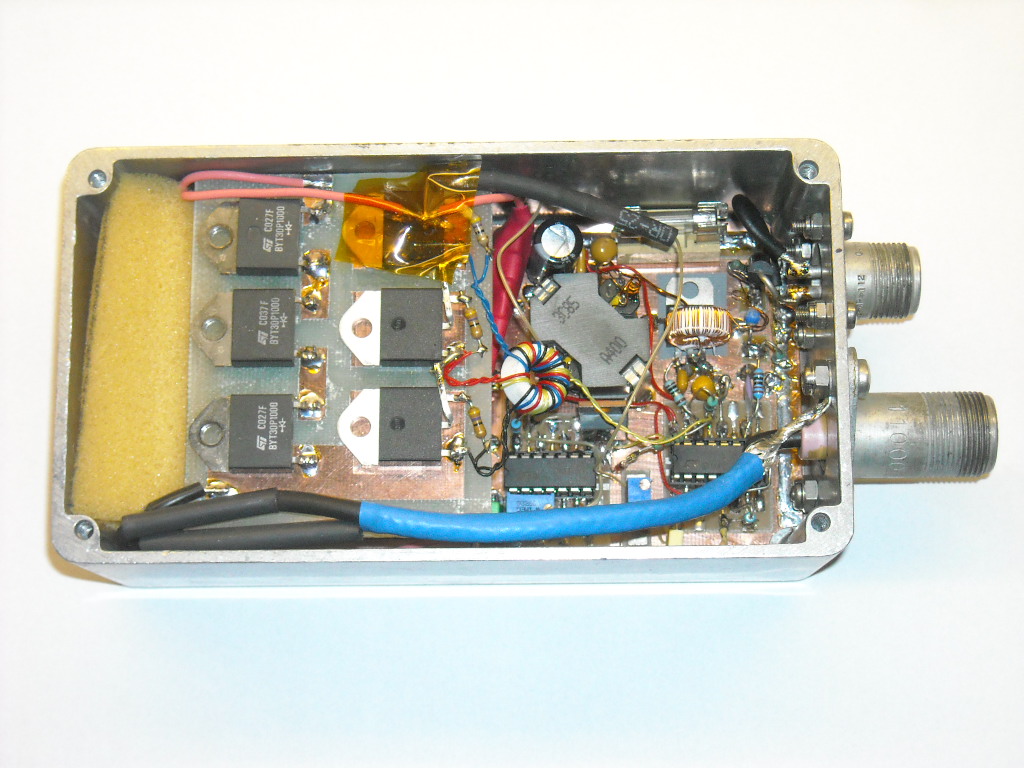 This looks alot more complex than the old unit. The plan was to build it up using printed circuit boards something I have not really tried before.
This semiconductor unit is essentially an inverter feeding a transformer followed by a voltage multiplier and a bank of small capacitors. In place of the spark gap we have a series of SCR’s (thyristors) that are triggered by a logic IC from the inverter circuitry. The circuit boards were made using photosensitive pcb’s and etched with ferric chloride. Not bad for a first attempt.
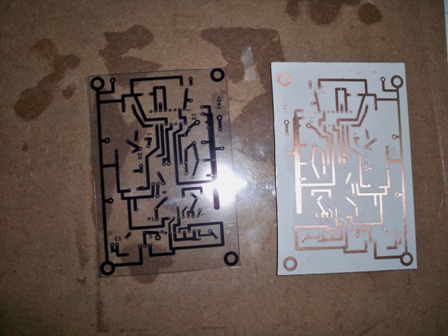 The boards came out really well but I should have put in a better ground plane which later resulted in a few problems when I tried to put it into the box. The next step is to install all the components and solder them into place.
Having completed the boards I tested the whole thing on the bench. Amazingly it all worked first time.
Here’s the video: http://www.youtube.com/watch?v=7QocOVDg-NI
Unfortunately, success was only short lived because as soon as I tried to install it in the box everything stopped working. The main reason for this was that the boards particularly the PWM circuitry did not have a ground plane between all the components and there was inadequate screening of the various inductors. The inverter runs at quite high frequencies making the IC’s sensistive to electromagnetic fields.
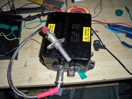
In the end I had re-do the PWM board and with a bit of fiddling I finally got it to work in the box. Here’s the finished product:
The lead is also a homemade item and again works quite well.
Amother video of the finished product
http://www.youtube.com/watch?v=vpWu-54nQ3s
Having successfully built up my all-semiconductor igniter box I turned my attention to a unit that I bought off E-bay several months back. This igniter unit was sold at a rock-bottom price of £15 as it had been tagged as U/S – unservicable. I’m not sure why I bought it as it was a sealed unit and the chances of getting it to work seemed remote. I guess the unit could be opened up and the parts used for something. However, my previous experience of these sealed units ( like the one on the M701) has not been good and I had expected the whole thing to be filled with resin making removal of the components impossible.
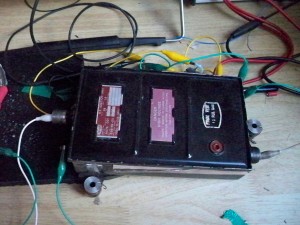
The igniter unit apparantly is from a Tornado jet and the outside condition is very good. When I got it a few months ago I put it on a shelf and forgot about it until last weekend when I decided to try and open it up and see what was inside. I took my angle grinder and carefully cut through the top. Inside was a whole load of cotton wool padding with the components neatly partitioned. It looked as though it used some sort of inverter with the standard voltage multiplier and capacitor arrangement but with a spark gap for discharge.
The only really accessible component was the power transistor and I had a feeling that this was probably the most likely thing to have failed. I removed it and replaced it with something similar from my junk box and hey-presto the igniter box jumped back to life.
Having found the details of the original transistor I bought a new one, inserted it into position and sealed the lid back on with some tape and a few cable ties. I now have a working igniter box, can’t be bad!
Here’s the video:
http://www.youtube.com/watch?v=QHl07Skdhrs
