(Keep scrolling down for latest updates)
AUGUST 2010

It’s very rare for a hobby jet engine enthusiast to ever have the opportunity to own a large turbofan that powers a commercial airliner. These are massive engines and simply moving them from A to B is a logistical nightmare. Furthermore, working engines that are time expired or near the end of their lives are still very expensive simply because of the high scrap value due to the precious alloys and metals they contain in significant quantities.
This RB211 had been abandoned at the local airport for several years and after a bit of wrangling with the airport owners I managed to secure it for my collection. The engine has spent some time outside under a cover and although complete has suffered some superficial corrosion. When I first saw it I was not convinced that running it was a remote possibility but after several inspections, it looked more and more likely that this engine was salvageable and with a bit of work could run again. Fortunately, the core of the engine has been protected not only by the external cowlings but the fairings of the gas generator. Most of the corrosion is limited to the bolt heads on the various accessories, the fan casing itself is in good condition, as is the core. The fan (N1 shaft) turns beautifully as does the IP (N2) shaft. The N3 or HP shaft has yet to be assessed as I need a gearbox crank -handle, but I’m not expecting problems. I’ll need to boroscope the inside to check all the blades to see if it is suitable to be fired-up and alot of preliminary work will need to be done such as instrumentation and confirmation that the fuel and lubrication systems are functional.
Moving this engine from the airport to my house required a 35T crane and a large lorry; here’s a picture of the engine being transferred onto the truck.

Here’s the engine neatly parked in the drive. She’ll stay here during the preparation period and hopefully I’ll move it to a special test area (once I’ve built it ) around the back.

The RB211-22B is quite an interesting engine and was one of the first generation of big turbo-fans designed and produced by Rolls-Royce to power the emerging market of wide-bodied jet airliners back in the 1970’s. Originally, this engine was developed for the Lockheed L1011 Tristar but later variants including the RB211-524 went on to power the Boeing 747. Today, the descendents of this engine include the very successsful Trent series of engines made by Rolls- Royce that are used on the Airbus A380 and Boeing’s 787 Dreamliner.
From what I can tell, this particular engine spent most of it’s life in the USA. It has TWA all over it so I presume it was from one of their Tristar’s. I guess it would have looked like this:

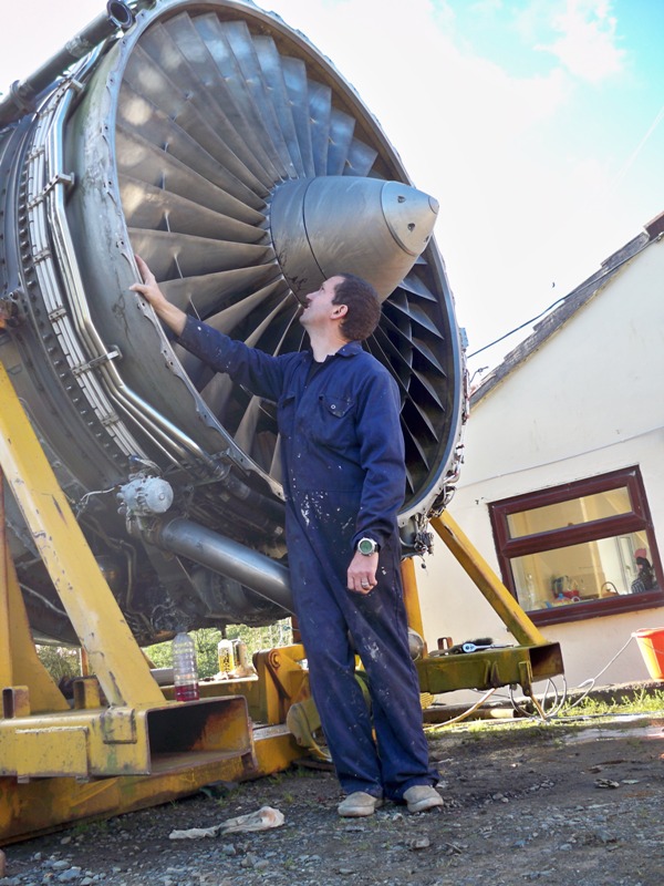
Unlike my other engines this turbo-fan is alot more complex; for a start it has three shafts with separate low, intermediate and high pressure compressors and turbines. At full take-off power it will deliver 42,000 lbs of thrust. Below is a nice view of the front fan, 33 blades of solid titanium. During the development of this engine the fan was originally to be constructed of a carbon-fibre composite (Hyfil), unfortunately the blades could not withstand the bird-strike test so they had to use titanium instead.

As you can see from the picture below, the wiring looks really complicated. It’s going to take time to figure this lot out and I haven’t got a circuit diagram yet! The two ignition exciter boxes can be seen from this view of the top of the engine. These run at 110v at 400hz, so that the aircraft’s APU can power them. I may have to replace these with a 24v unit.

Another view of the control signal amplifier unit and associated electrics:

September 2010
I have started the cleaning up process on the engine and so far most of the corrosion on the accessories is coming off quite easily with a wire brush. A small sandblaster has proved useful for the difficult to reach parts and it is quite rewarding to see all the bolt heads return to their former stainless steel glory. To finish everything off I spray a homemade cocktail of kerosene and inhibiting oil over the surface. This not only helps to clean but will protect the components from further corrosion.
Good news!!! I have manged to find an air-start turbine for the 211. Hopefully should be arriving soon. I had to track one down in Thailand of all places. Many thanks to Jeff from AGS, breaker/scrappy of L1011’s for sorting this out.

DECEMBER 2010
Things have been fairly quiet over the last few months and I have wrapped the RB211 up in its covers for the winter. It’s really been too cold to do any work on it and I doubt I’ll be doing much until the spring.However, I do have a couple of smaller projects to be getting on with including preparation of the test stand caster wheels and the electrics.
STATIC PHASE INVERTER

The various electrical sensors and actuators on the engine use a combination of 24v DC and 115v 400Hz AC. Although 24v DC is easily obtainable using batteries, the 400 Hz supply is a little more awkward. I am hoping to use most of the original sensors on the engine such as oil pressure, temperature, fuel flow etc and therefore we will need a source of 115v 400 Hz. This will also mean we can use the original ignitor boxes on the engine. Ian Bennett and his brother Paul visited a few weeks back and we tested the ignitor boxes with his portable 400Hz supply. Both boxes worked perfectly and it was great to hear the clicks of the high energy plugs firing. One small step to getting the engine running!
For my AC supply Iam going to use an old aircraft inverter…..the older rotary types are heavy and awkward so I have found this little gem (above) off E-bay, a solid state static phase inverter. The static inverters are usually smaller and often more expensive (several hundred pounds) than the rotary types, this one was somewhat of a gamble as it was untested but it was worth it in the end as it only cost £25.
As you can see from the picture, there are no clues or markings as to the pin- out of the inverter, the only info I have from the seller is that it is 24-28v input and 115v out. Here’s the inverter with the back removed. I need to trace the wires from the plug connector to determine the most likely input leads; we can then use the multimeter and the oscilloscope to check the output voltages and frequencies.

This old inverter probably dates to the sixties or seventies, the components are beautifully laid out and it’s easy to follow, not a single PCB or microchip to be seen. Having connected up my 24v supply to the input, I can clearly see on the ‘scope the 115v 400 Hz waveform, a perfect sine wave!

Iam quite chuffed that this little inverter works so well and hopefully should be sufficient to power my instruments and at least one of the ignitor boxes. Next stage is to start work on the heavy caster wheels of the stand so we will be able to move the engine.
JANUARY 2011
AVIONICS & INSTRUMENTATION
Oil Pressure Gauge and transmitter
Its New Year’s weekend so I have decided to try and figure out the pin-outs on my oil pressure gauge and at the same time test the oil pressure transmitter,- a nice little job that can be done indoors.
Fortunately there are quite a few genuine L1011 instruments that come up on E-Bay quite regularly. I bought this L1011 oil pressure gauge a while back with the intention of using it on my control panel. There is a much better chance of getting them to work with the transducers and sensors that they were originally designed for. As usual I have no idea of the pin-out for connections. Scouring the internet for this information has also been fruitless which means that I’ll have to take it to bits and figure it out for myself.
Below is the gauge in question. I think it is a synchro type as it has a fair amount of electronics inside and a small transformer for powering the instrument and the sensor. I would have expected a ratiometer to be more simple.

Here’s the rear of the gauge. The connecting socket has 15 pins. The only info I have is that the background light is connected to pins 1 and 2 and the instrument requires 115v 400hz.
In order to test the gauge I have removed the oil pressure sensor from the engine. We know this is a variable inductance type sensor requiring 26v 400 Hz. By measuring the resistance it appears this sensor consists of 2 coils in series tapped in the centre. The resistance and voltage from the transformer in the gauge should tell us the input and output pins. There is also a 5v DC input for testing the movement. Below you can see the oil pressure gauge and the sensor all wired up. Using a syringe filled with oil I can see that my pin-out deductions are correct as we get a nice deflection of the needle as pressure is applied to the sensor aperture.

All I need to do now is put it all back together and try and find a suitable connector for the indicator. If anyone has a similar oil pressure gauge I have placed a link to download the pin-out connections.
L1011 Oil Pressure gauge Pin out
FEBRUARY 2011
Now that the snow and ice has gone I have decided to get back outside and do some more work inside the engine. One of the things I have been meaning to do for a while is to have a look inside with a borescope. Professional borescopes using fibreoptics similar to the ones used in medicine are extortionally expensive. I therefore have bought a cheaper mechanics type that uses a small camera on the end of a flexible shaft with an lcd viewing camera. It’s not billiant but the image quality is good enough to see the state of the compressor and turbine blades.
The engine has several viewing ports along the sides enabling the different stages to be examined.

With the limited views available I can see that there are no major defects with the blades in the HP, IP and LP stages. Some of the stator veins in the compressor have some superficial oxide deposits but the rotating assemblies look OK. If we get the engine running most of this will probably come off and a compressor wash should also tidy things up.
MARCH 2011
Things are really starting to move now with the RB211 project. Over the past few weeks I have had one of my neighbours, a local farmer, prepare the test area and the new site where the engine will be parked and housed. This has involved flattening and levelling an area in my field.

In order to provide a level surface for the transportation frame to run on I will be putting down a plastic modular floor. Once everything is in place we will need to get the crane back in to move the engine to it’s new home and at the same time fit the caster wheels and the nose cowl back on.
CONTROL BOX
I have made up a control box for the engine and just need to complete the internal wiring.

For my box I am using an old ammo box. Within is a welded steel frame that has an aluminium front panel to mount the instruments, this allows the frame to be withdrawn from the box completely.
The engine speed indicators are 3 digital Infinity RV-2 gauges by MGL Avionics that are programmable to the desired RPM of the N1, N2, and N3 shafts respectively. I had intended to use original L1011 indicators here but battled to find the right ones as the synchro gauges are usually engine specific.Below you can see the 3 speed gauges, the only issue now is match them to the engine sensors.

We also have oil quantity, oil pressure and Turbine Gas Temp gauges that are all TriStar instruments. The oil temperature gauge is a standard Weston type.
In the middle is an original L1011 Turbine Cooling Air warning panel from the upper section of the Flight Engineer’s Instrument panel. I think this will give it a nice finishing touch. Next job is to wire it all up.

The wiring in the back of the control box looks a bit of a rat’s nest but it should all work. Funnily enough, there’s no circuit diagram as such except the connector pin-outs, everything is very much ” make-it-up- as- you- go- along”, kinda like vascular surgery!!

CASTER WHEELS
Originally the transportation frame was fitted with 4 caster wheels, however these had been removed at some stage and as a result of the elements were in a very sorry state when I obtained the engine. Each caster wheel unit weighs about 30 kg and consists of two 8-9″ diameter iron wheels on a single axel held together in a heavy duty steel frame. The wheels have an in-built suspension system made up of 3 springs that are attached to the wheel axel supports. For some reason the spring retainers were extremely rusted and corroded to the extent that I had to replace them. Here’s an example of one of the wheel units before it was cleaned and repainted:

You can clearly see how corroded the spring retainer is. Most of the wheels have lost or damaged tyres that will need to be addressed and because of the cost involved in replacing them with plastic tyres I have decided to remove them all down to bare metal and coat the running surfaces with Flexane, a brushable liquid polyurethane compound. This should provide some support and reduce the stresses on the modular flooring of the test-bed.
Andrew at Cross Engineering has made up some new spring retainers for me so all I need to do now is put them all together. The wheels look alot better after a coat of paint and once the Flexane has been applied they will be ready to go back on the stand.

APRIL 2011
More Electronics…..
The control box is now pretty much complete and I am quite eager to test the various gauges particularly the digital RPM indicators. This is quite a problem as the only way to find out if they work or not is to connect them up to a running engine or at least during a motoring cycle with the starter. The engine utilises two methods of RPM speed detection on each of the rotating shafts. The N1 and N2 shafts use variable reluctance magnetic speed sensors (phonic wheel) while the N3 shaft uses a traditional tachometer generator off the high speed gearbox. The problem I have is that the signal from the N1 and N2 sensors are too weak to be recorded by the RV-2 indicators and therefore require some form of signal conditioning to interface the transducer to the instrument.
I have built up a small signal conditioner using 2 LM1815 integrated circuit chips, one for each channel. Essentially these chips will amplify and filter the incoming signal from the sensor and send a 6.8v pulse to the indicator every time a gear tooth passes the sensor face. Here’s the black box of electronics that contains the signal conditioner:

Having built up this little unit I tried testing it on the engine by connecting up to one of the sensors and turning the N1 shaft by hand. Unfortunately I cannot get the rear turbine to spin much faster than 10 or 12 RPM and the gauge records absolutely nothing despite the fact that there is an output from the signal condtioner seen on the scope. The only way to test the gauges is to build a home made gear tooth sensor and run it with an electric drill, so here’s my DIY test rig using a variable reluctance sensor from a car and a drill.

Despite some interference of the signal from the motor my home made signal conditioner and the gauges seem to work a treat…we have our RPM reading!!

The digital gauges and the signal conditioners seem to work; I’ll need to perform further tests at a later stage with the engine motoring on the starter. For the moment the control box will be put aside as I need to prepare the engine nose cowl ready for it to be re-installed when we move the engine to the test area next week, keep watching, ’till next time….
…………………………
In preparation for the lift next week I have removed the front fan cover in order to clean the LP compressor casing as once the nose-cowl is fitted this might be more awkward. I took this photo of the engine -core from within the coldsteam duct. The fairings of the gas-generator have been removed for cleaning/painting. In the foreground are the fuel feeds for the burners and at 2 o’clock you can just see the variable inlet guide vane actuators and rams. At 5 o’clock is one of the compressor bleed valves. The core has had a good clean-up and the inlet guide vanes behind the front fan have been re-painted.

NOSE COWL
The nose cowl of the engine is the front air intake that surrounds the fan. This had also been removed and has been sitting on a rotting pallet for a number of years. The nose cowl, apart from providing an aerodynamic flow of air into the engine, contains a number of pipes that contribute to the anti-icing system by directing warm air from the compressor into the coldstream duct and the main core. Obviously, ice is not going to be an issue for us as the engine is going to remain firmly on the ground so there is no requirement to service any of this extensive plumbing.
Originally the nose cowl was bare aluminium, however after spending much time outside and probably not cleaned that often even when in service the metal is tarnished with a thick layer of oxide. With the hot weather we have had lately I have decided to start polishing it up. Below you can see the metal shine coming up nicely as it is restored to its former glory. I think it’ ll take a few go’s before it’s really mirror finish.

Inside the nose cowl the aluminium sheet is perforated with hundreds of small holes to allow the air through. This was even more oxidised than the ouside requiring a sander to remove the dirt. The finish has a brushed aluminium look to it. Below is a picture of the inside of the nose cowl, note the P1 pitot tube for measuring the engine pressure ratio (EPR). Unfortunately the leading edge has taken a ding at some stage and there is a small hole that will require a repair job.

THE BIG LIFT 26th April 2011
Right on schedule the crane arrived this morning to move the RB211 to it’s new home at the back of the garage. I think this came as a welcome relief for my long suffering wife, Elize, as she can now park her car alot easier in the drive!

Once the engine was sited on the ground the next job was to fit the caster wheels and the nose cowl. I have to say that this went much smoothly than I had anticipated given the weight of the wheels. It looks as though that even with the wheels attached the engine is going to have to continue to remain immobile as the plastic modular floor is unable to cope with the weight. Although the modules remain perfectly intact they deform particularly under the bare caster wheels making the surface too uneven to be able to pull the engine along as I had originally hoped. This will not be a major setback as I will construct the test gantry around the engine and build a movable storage shelter/tent to keep it dry. The flooring will come in handy later.
Now that the wheels are in place it’s on with the nose cowl…

I have to say that the nose cowl makes a big difference to the sheer size and presence of the engine; it’s really starting to look like it’s just been removed from an L1011 or a 747!

I took this short video clip of the fan wind-milling in the breeze, it was starting to pick up up a bit of speed and you can easily hear the characteristic clack-clack sound of the clappers on the blades.
http://www.youtube.com/watch?v=qv0sBTvpcOg
JUNE/JULY 2011
The last 4 to 6 weeks have seen little work on the engine itself as I have been busy putting together a tent shelter. Because of the weight and sheer size of the RB211, moving it is a major undertaking therefore I decided to put my shelter on wheels and move it off the engine when required. The storage tent is actually a boat-shelter by Dancover, one of the few suppliers of temporary canvas garages or shelters. Prior to erecting the frame I built up a large frame from steel and wood to which the base plates are bolted to. The whole structure sits on 6 wheels and works a treat. I guess the real test will be how it stands up to the winter gales!

Now that the engine is undercover I can remove some of the tarpaulines and start with the re-wiring. The tent-shelter is brilliant and is like a huge hangar. Here’s another keen member of my ground crew (Danica) checking out the front nose cowl.

This weekend I have decided to start the re-wiring process. Essentially this involves bringing out connectors and wire from the various sensors and actuators so that they can interface with my control box.
The day started well with work at the top of the engine and both ignition exciter boxes complete. Next was the turn of the High Pressure Shut Off Valve (HP SOV). According to my L1011 handbook this is powered by 2 seperate “open” and “shut” circuits with 28v DC. When I came to test the connections everything is open circuit and totaly dead. This may be due to a faulty connector or something wrong with the actuator or its switch -gear. Unfortuately the HP SOV is not very accessible due to the myriad of plumbing surrounding it and I can’t remove the electrical connector as it is right at the back, I suppose I will have to remove the whole thing and check it out on the work-bench.

Well,it took the best part of a day to remove this little bugger; I hate it!! anyway, here it is. The switch gear casing looks like it has been broggled with sometime in the past, probably a minor modification. This might explain why I was getting open circuit readings with my meter.

The actuator seems to work although I’am not entirely sure why it won’t with 28v applied to the pin connectors, maybe a faulty wire somewhere. In any event, I have decided to re-wire the whole thing to work with my control box. This will mean a bit more extra work fitting a relay and other circuits to reverse the polarity of the actuator motor.
Here’s the HP SOV after the cover of the switch gear has been removed. I have re-wired this and tested it with a 3PDT relay and it works a treat. All I have to do now is put it back together and place it back in position.

It’s been a busy on-call week at work but I’ve still managed to slip in a few hours on the engine. The HP SOV has been re-installed and is now working as it should. Just when things appeared back on track another problem has sprung up. This time it’s the HP Bleed Valve control solenoid. This solenoid valve controls one of the air bleed valves on the HP compressor and maintains it in the open position during start up. The P4/Pf pressure switch disables it at 68% N3 or by manual operation using a switch on the control panel. When I came to testing it there was also an open circuit suggesting a possible electrical malfunction. Fortunately this unit was alot easier to remove than the HP SOV and after removing the socket I found a dry joint on one of the connectors. A quick re-wire and it’s working.

Interestingly, according to my RR manual the HP Bleed solenoid valve often causes problems on the 22B and I just wonder if it is something to do with the quality of the solder joints on the connectors of this particular component.
N3 Tachometer Generator
As I have now started the engine wiring I have decided to remove the N3 tach generator in order to bench test my digital RPM gauge.I had left this to last as according to the instrument manual this should be just a simple matter of connecting up to the gauge without the need for any additional electronics; how wrong that proved to be!
The digital RPM gauge is designed to work with most tach gennys, where most refers to the standard 2 or 4 pole variety. The RB211 uses a 12 pole type and the output undergoes signal processing in the speed gauge itself. Initially, I tested it using a standard mains operated electric drill and got all sorts of spurious readings that kept me busy trying to figure out what was wrong. Essentially,the AC was interferring with the signal and it wasn’t until I switched to a cordless drill that this problem became evident.Furthermore, I then sussed out that the tach gen casing had to be properly earthed. In order to allow the RPM gauge to detect the output signal a squaring amplifier was required to provide a clean series of pulses corresponding to the RPM. Problem solved, but it took a week of frustration. I am now getting stable rpm readings although the resolution below 18% N3 is somewhat poor. We may just have to accept this. Below is my squaring amp based on a LM3900 IC.

AUGUST/SEPTEMBER 2011
The last couple of months have been busy trying to get the electronics finished and the starter fitted so that we can see how the Stad Air Start Unit works on the RB211. The starter turbine was fitted without any great dramas although the mounting bracket was removed for a coat of paint. I’m using the original stainless steel ducting and the air start control valve that came with the engine. The air hose will fit directly onto the valve and secured with a v-clamp. Here’s the starter in position.

The air starter shut- off valve is shown below. It’s pneumatically operated following initiation with an electrical signal via a solenoid. A switch also illuminates an LED on the control panel once the valve is open.

Most of the engine re-wiring is now complete. All the terminals enter this junction box before connection to the control-box. I am using two fifteen meter multicore cables to connect the box to the engine.

A few weeks ago Ian and Paul Bennett came down and we successfully dry motored the engine on the starter. The N3 tachometer appears to be faulty despite my homemade amplifier and it has since been replaced and should work next time. There were one or two minor gremlins to sort out but overall I’m quite pleased with the the progress so far.Here’s a video of the dry run:
Another video of the run as shot by Paul:
REAR ENGINE MOUNTING SUPPORT
My next big job with the RB211 is to somehow reinforce the transportation frame and provide support to the rear engine mounting. At the moment the engine is supported in it’s transportation stand by two support struts on the front compressor casing. This is not an ideal arrangement as it leaves the rear of the engine and the core largely unsupported leading to vibration and potential dislodging of the whole engine. Therefore the front and rear engine supports will need to be attached to the frame which will be in turn be set to the ground using steel girders into concrete fixings.
I had hoped to simply bolt the modified frame onto the existing titanium plate, however, the original bolts are 1″ UNF and impossible to find as this is a non-standard bolt size. I have had to remove the original captive nuts and will replace the bolts with more standard metric sizes. Here’s the rear engine mounting plate.

The hole in the centre would have accomodated the pylon shear pin which I understand is quite an expensive piece of kit. You’ll also notice that there is angle of about 15 degrees on this plate; this will require an adapter so that my cross-bar will be horizontal to the plate/mounting assembly. In order to access the underside of the rear mounting and the captive nuts a panel has to be removed. Unfortunately most of the screws have seized and had to be drilled out; a very time-consuming job as they are made of stainless steel.
Below you can see the upper-rear end of the engine with the panel removed. The air-motor for the reverse-thrust system and associated piping can be seen in the centre of the picture.

While I have been working on the rear engine mounting I have also decided to do a bit more polishing on the nose -cowl. This is really a laborious job but will be worth it in the end!

December 2011
I’m waiting for decent weather before I can finish off the transportation stand gantries. The tent shelter has stood up quite well to the recent windy conditions and the drop in temperature also brings a slow down in the work done outside. On the occasion I have managed to get outside I have noticed that the cold brings in condensation into the tent and onto the engine. So to prevent all my hard work from corroding again I have invested in a second hand de-humidifier. I have stuck this in the nosecowl up against the front fan and using a small fan this blows dry air through the engine.

The gas generator fairings that were removed earlier this year have now been given a good clean and a new coat of paint. I’m going to paint the forward sections white and the rear combustion chamber covers silver.

Most of the fairings were in reasonable condition despite being very dirty. This was not the case with the rear turbine/exhaust fairing. This cover is the largest piece and when I removed it when the engine arrived it was in a very sorry state indeed. Water had been collecting in it and the aluminium skin was severely corroded with multiple perforations to the underside. I had contemplated removing all the aluminium skin and replacing it; however as the rest of it was OK and the difficulties working the metal into the correct shape with my limited resources I decided to simply sheet over the affected parts with some new aluminium. Although the result is more functional than cosmetic I’m quite pleased that it looks pretty good. Thank goodness it’s never going to fly again and we don’t have to worry about a CAA inspector having to look at it!

The next job I have decided to tackle is the exhaust duct. This had also been exposed to the elements and required a good clean up. As you can see from the photo the exhaust cone and the guide vanes are coated in a thin layer of rust. Apart from this the structual integrity is fine and there are no major cracks that require repair.
 After a good rub-down with a wire brush and sandpaper the exhaust looks a hundred times better. To finish it all off I have applied some very high temperature paint to the cone and the guide vanes to protect against future corrosion. I initially was in two minds about whether to paint the exhaust or not.However, the paint is rated to 650 degrees C and is further downstream of the main hot section of the engine. In this engine we would abort an attempt at starting as a hot-start if the EGT got to 550 degrees C. So I think the VHT paint should be OK.

In this picture the LP turbine looks very impressive and the exhaust duct now looks presentable. The next job will be to tackle the transportation frame.
January 2012
Once again it’s New Year’s weekend and I’ve spent most of it in the shed/tent. After several months of cutting, drilling and painting the steel girders and plates of the transportation frame supports Iam now at the stage where everything just need to be put into position and bolted together.
The plan is to make a square arch attached to the rear of the frame that will then support the rear engine mounting. A similar system will be used at the front. The beams I am using are 150×75 mm steel channel section with supporting gussets made from 6mm steel plate.
To erect the rear beams I have had to move the tent off the engine and with the help of my digger, bolt them to the stand. Unfortunately, work was cut short by the weather and I’ll have to wait for a dry weekend before I can complete the work. Here’s one of the rear beams in position.

Drilling steel of this thickness is out of the question using a conventional drill and bit so I am using a magnetic drill which makes light work of drilling steel that is up to 10mm thick in places.

The challenge will be mounting the horizontal sections as I will be working at the limit of the digger’s reach; will just have to wait until this rotten weather improves to find out.
7 th January 2012
Amazingly the weather this weekend has had no rain so it’s back to work outside. The shelter is off and I’ve almost completed the supports for the front and rear engine mounts.
The horizontals are in position and I will add a further 2 struts of box section to link the front and rear supports in addition to the diagonals from the rear into the ground.

FEBURARY 2012
Over the last few weeks I’ve had a few e-mails from various people interested in the project and offers of help in sourcing parts. Many thanks to all of you and keep watching the blog for updates as I think we should be good to go for a start-up attempt in the next few weeks.
John Goodale who works at Rolls sent me an interesting e-mail enquiring about the history of the engine and kindly offered to do some detective work to see if Rolls Royce had any service info on my RB211. It looks like the last time RR had info on it was in 1992 and at that time it had done 44,544 hours and 13,910 cycles. According to John that would correspond to the time that TWA retired their Tristar fleet. Asssuming it was removed from an L1011 at this time and not put back into service which I think is what happened, the engine is middle-aged with plenty of hours and cycles still left.
The work on the frame is now complete and the front and rear engine mountings have been secured to the newly fitted crossmembers. The engine feels alot more secure than before. I was planning to incorporate some form of anti-vibration mounts on the engine supports but could not find anything suitable. I don’t think that this will be a major problem as most of the vibration will be absorbed through the frame and the springs in the caster wheels plus the plastic modular flooring. Here’s the rear engine mounting complete with the steel box section adapter:

The front mounting is sandwiched onto the beam with a 10mm steel plate and four large bolts.

I have also re-painted the transportation stand as this was looking a bit tatty.

The remainder of the gas generator fairings have also been cleaned and re-painted and are now back in position. The cold stream duct itself could do with a new coat of paint but I think this will wait until after we have tried to run the engine.

This picture gives you an idea just what a state the fairings were in before re-furbishment:

There’s not much more to do now, the fuel line from the tank will have to be connected and hopefully will not leak like the last attempt I tried this. The fuel system will then need to be primed. I have some final wiring to do for the EGT thermocouples that should not take long and the Stad 250 start cart needs a tweek to get as much air out of it as possible for starting.Keep watching!!
MARCH 2012
Two weeks ago I ran the engine again on the starter this time with a functioning tach genny. As I guessed the maximum motoring speed I can achieve is 15% N3 which is well short of the recommended 20-25% required for safe starting. My tech info does suggest that two air start carts are usually required to start an RB211, however one has to remember that in the usual aircraft position there will be at least 15m of ducting between the air-start coupling on the fuselage and the engine starter. I had hoped that the reduced power of just one cart would be off-set by the lack of dead space due to the fact that Iam connecting the air delivery hose staright into the air turbine motor. Alas, not the case, so I will have to find another source of air and adapt the starter piping to accomodate two hoses.
Fortunately I have found another Stad 250 engine courtesy of Harry Thompson which I hope should do the job once I have prepared it. Here’s what it looks like:

Click on the picture for more information and progress on how I get this engine up and running.
JUNE 2012
The second STAD air starter is now up and running but I do not have an air-start hose to connect it to the engine. Initially I decided to try using a 70cm diameter old firehose as this appeared to work with Adrian’s AI-25 engine. However, after fabricating the various couplings it proved inadequate and unable to crank the RB211. In the end I decided that I would have to get a proper jet air-start hose, not an easy decision as they don’t come cheap.
In order to connect the two start-cart hoses together I have made up a Y-connector adapter. The adapter consists of a 4″ diameter Y- splitter that is actually from a car exhaust system (boy-racer type). I have welded a non-return valve on each end so that the back pressure from each hose output does not interfere with the other.
The non-return or check valves came from the US via E-Bay and according to the attached paper-work originate from a couple of old Fed-Ex Boeing 727s that are now sitting in the Mojave or Arizona desert. Here’s the new coupling with air-start hoses attached:

5th June 2012
It’s the Diamond Jubilee weekend and I’ve invited a few friends over for an attempt at starting the RB211. After a week of rain we finally get a dry day to push back the tent-shelter.
It’s quite nerve racking as I have not run the two STAD’s together and I don’t know what sort of speed they will crank the engine. After a bit of preparation we are ready to go. I control the new STAD, Jon is looking after the start-cart and Adrian will operate the RB211 control box. The new STAD needs alot of attention as I believe the fuel system is not perfect and has to be controlled with the speed valve continuously, it certainly does the job and delivers air just as it should.
With both STAD’s running, we throw the switches and the air hoses jump and become rigid with pressurised air. I signal to Adrian to release the start-air valve on the RB211 and immediately the N3 gauge starts to climb to 20 then 25% N3. The huge front fan starts to turn and gather speed. The igniters are on and Adrian opens the High Pressure Shut-Off valve and fuel flows into the engine. The TGT starts to rise and we have a successful light-off. At this point I have my back to the engine and I’m concentrating on the STAD, I can hear the characteristic rumble of the RB211 as it slowly comes to life. There’s a bit of smoke from the tail pipe as expected, we reach 50% N3 and I signal to Jon to return the STAD to idle in order to cut the air to the starter. The engine reaches it’s idle speed of 63% N3 and the noise is terrific. The engine works perfectly as if it had only been started after a recent inter-continental flight. We run the engine for 15 minutes but have to shut it down because of an unexpected fuel leak on one of the hose junctions. A quick fix followed by a tea-break and we’re ready for another run. Once again the engine starts perfectly despite one of the STADs playing up. Another 15 minute run and at the end of the day we’ve used 400 litres of fuel. I have seen and run many jet engines in my time but this one is absolutely fantastic.

Various pictures of the day courtesy of Adrian can be viewed here
Video to follow!
And here it is: