The idea of using an automotive turbocharger as a jet engine seems at first to be inconceivable, however, given the job that it does in an internal combustion engine this concept actually makes sense. I originally thought about building a pulse jet engine but a turbocharger based engine seemed more of a challenge. If you are contemplating a hobby in jet engines, building one of these is a good place to start as it demonstrates the basic design principles on which most gas turbines are based, that is an air compressor, a combustion chamber and a turbine. In a commercial jet engine these sections are arranged axially, one after another, however, in a turbocharger based engine they are radially placed. This allows simplicity of construction at the expense of efficency.
What Type of Turbocharger?
The golden rule here is the bigger the better. Something from a large diesel engine such as a 4×4, truck or large generator. It needs to have an inlet of about 2.5 to 4 “, no waste-gates and no bifurcated turbine scroll. I was lucky to find two large Schwitzer turbo’s off E-Bay that were going cheap and were ideally suited as a jet turbine. They are both enormous and dwarf the turbo on my 200 Tdi Landrover. Each weighs in at 25 kg. You can source turbochargers from a scrap merchant, but these are not always in good condition with poor bearings and damage to the vanes. New turbo’s suitable for DIY jet engines are available but expect to pay a small fortune.
ConstructionThe essential components required to build our jet engine in addition to a suitable turbocharger include a combustion chamber, an oil circuit and a fuel delivery system.In addition we will need monitoring of the various engine parameters including oil pressure, P2 (combustion chamber) pressure and the exhaust gas temperature(EGT).Here you can see the finished engine mounted on a frame. The combustion chamber is situated top left and contains an inner flame tube where the fuel is burnt in air under pressure. The compressor outlet enters the CC at the top end of the chamber with the outlet bolted directly to the turbine flange.

A silicone air hose is used to connect the CC to the compressor outlet.Surprisingly this is quite heat resistant given that it is attached straight onto the combustion chamber. So far it has shown no signs of melting and it still doesn’t leak.
Oil System
A reliable supply of oil is critical to the running of the turbo, not only for lubrication but for cooling purposes. In this design I used a small electric motor driving a steering pump from a car. The flow and pressure is regulated by a simple shut-off valve with the spill returning back to the oil tank.Drainage of oil from the turbo must be through a large hose with no restrictions under gravity otherwise the turbo will leak oil as I found out the hard way!
Below you can see the oil pump system. I used a large resevoir in the form of a jerry can so an oil cooler was not necessary.
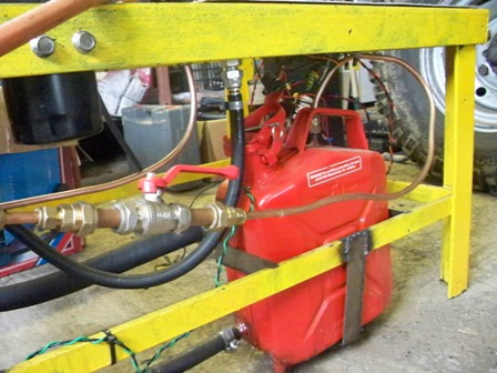
You can see the simple arrangement I used to pump oil around the circuit. The motor is rated at 5 Amp and uses a belt (from
a vacuum cleaner) to power the steering pump. The control valve regulates the oil pressure from about 20 to 70 PSI. At the moment I am using standard ATF in the circuit and this seems to work fine.

Fuel And Ignition System
This engine will initially be run on propane gas which makes the fuel delivery system relatively simple. I used a welding regulator and a flash-back arrestor directly connected to the combustion chamber. A needle valve controls the flow of gas and acts as a throttle. A spark plug rigged up to a coil and ignition booster + relay switch provide a reliable spark for igniting the propane.
Engine Monitoring
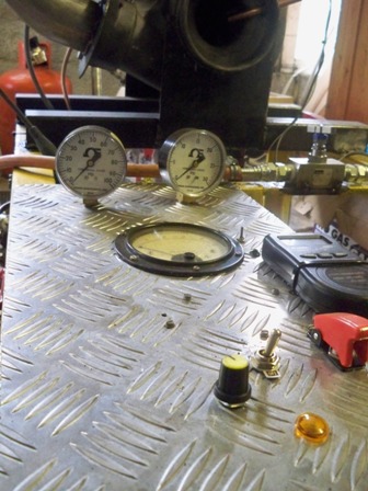
We are going to need some gauges to monitor the various engine parameters if we are to run the engine safely. A 0-100 psi gauge measures main oil pressure and a 0-60 psi gauge is used for the P2 pressure. A k-type thermocouple attached to a thermocouple meter (cheap from maplins) is used for the EGT. I bought a cheap optical tachograph from Hong-Kong via E-Bay and removed the laser diode and photo detector from the pcb and mounted them in a copper tube next to the inducer spindle. A piece of reflective tape has been glued to the spindle and reflects the signal back to the detector. This system costs about £20 and works very well. Alot easier than building one from scratch.Here’s the main conrol panel. The large meter is redundant, as is the motor speed control pot.
OPERATION
In order to start the engine, propane gas is trickled in with a gentle flow of air from the leaf blower into the turbo inlet. A pop is heard as the propane ignites and the EGT should start to rise. Once ignition has been achieved, I open the throttle valve and apply the leaf blower at full wack to spool the turbine up. As the turbine increases speed the characteristic jet whine will be heard and the engine will self sustain. Idle speed is about 25,000 – 30,000 RPM. I have not been able to achieve anything faster than about 45,000 RPM, simply because I can’t deliver propane at a faster rate. I know there are tricks like turning the bottle upside down and using liquid propane, but these methods are a tad unsafe to say the least.
Watch A Video Of The DIY Turbojet In Action