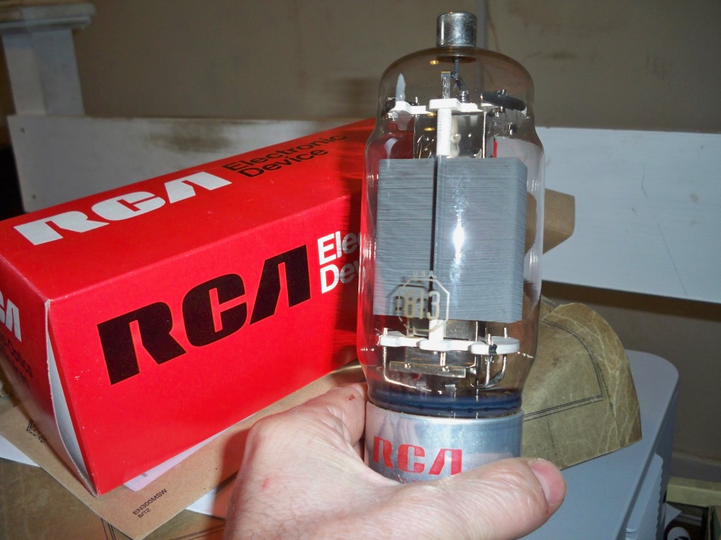
I’ve always wanted to build a massive linear amplifier since I was at school. In fact my old friend John Weston (G3LYW) gave me an 813 to use in an amp, I built up a power supply for it but never completed the linear so I’m going to have another shot at it!
I’m planning to build a linear based on two 813 valves in parallel and in the traditional grounded-grid configuration. The 813 is a good general purpose beam power tetrode and used to be popular with amateurs in the old days as a power amp valve. Not only does it do the job it looks the biz with it’s bright yellow/white filament.
Building a large power amplifier is really two projects in one, the power supply and the amp itself.
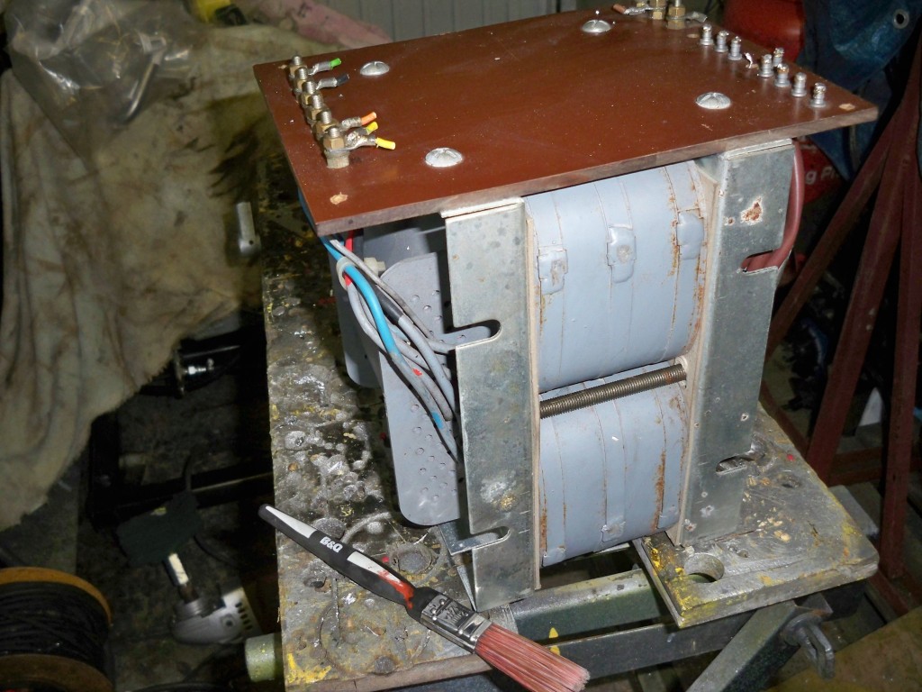
First up is the power supply. The 813’s need about 2.5kV for the anode and the filament needs 10v at 5 Amp so we are going to need a BIG transformer. So here it is…. this was bought of a fellow amateur via E-Bay.
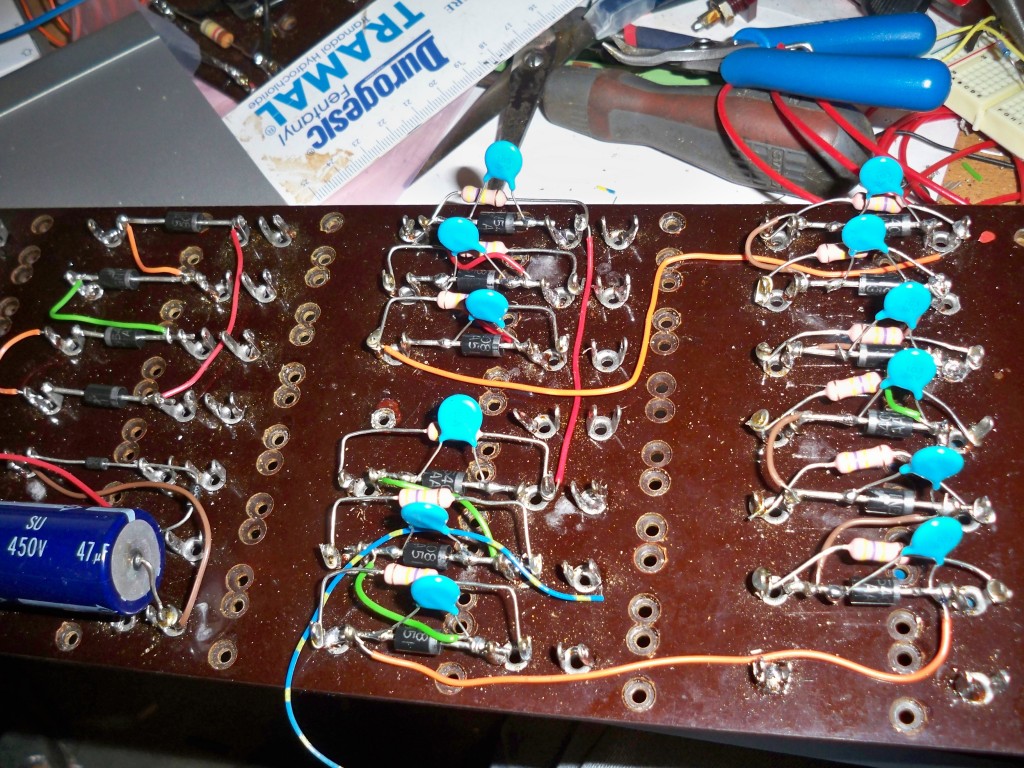
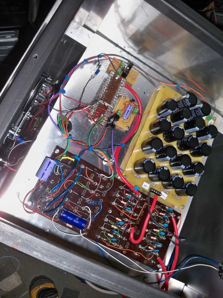
The transformer’s secondary is 1000-0-1000v at 1 amp. I’m going to use a standard bridge rectifier circuit with capacitative filtering to get my 2kv. The rectifiers are standard 1n5408’s in series to increase the voltage tolerance. Here’s the rectifier board with the diodes plus equalisation resistors and caps.
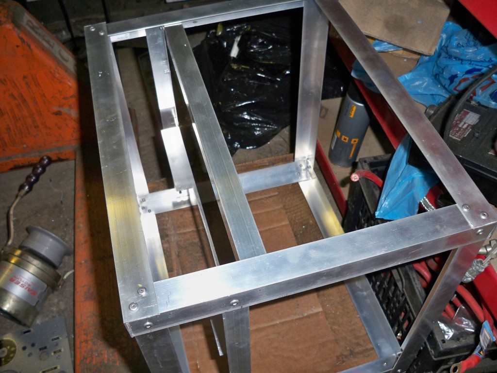
The chassis is fashioned from aluminium and steel, ultimately it will be the size of a small cabinet.
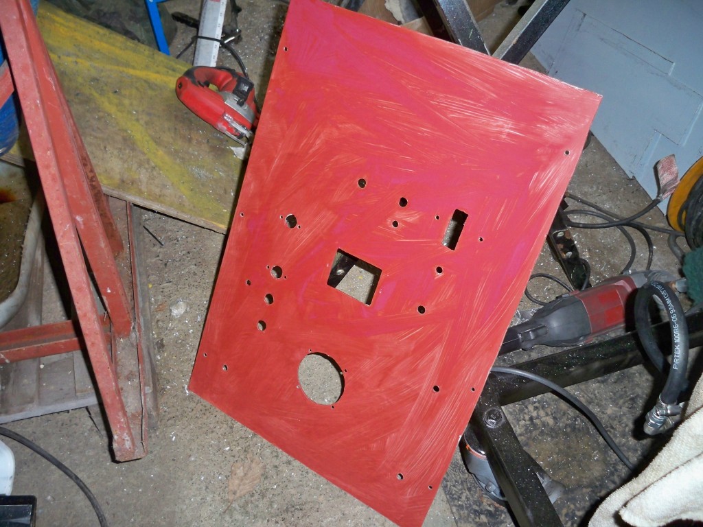
The front panel has been primed and is ready to be spray painted.
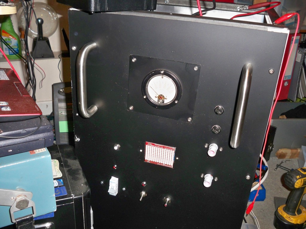
I’ve finished all the metal-bashing, now onto the wiring. The front panel is relatively straightforward with a circuit breaker for the mains and a couple of switches for the HT and LT supply. The meter is an old vintage type from an aircraft test set that I will adapt to read 5Kv FSD with a string of multiplier resistors. I did try using standard 1/2 watt carbon film resistors but they were starting to fizzle with the HT on 1400v! not even full voltage! so I’ll have to find some with a higher rating.
The square in the middle is a SMD Arduino LOL shield that I have programmed to scroll DANGER!! HIGH VOLTAGE. It was sitting on my desk with nothing to do so I thought it would add an interesting” finishing touch” as they say.
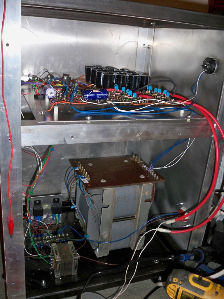
You can see the main rectifier boards and the capacitor bank mounted in the upper section:
Here’s another view of the transformer in the lower deck. The small accessory transformer is in the foreground with the relays and switch-gear at the rear. The whole set-up looks complicated but is just a bigger version of an i-Phone charger.
MARCH 2013
I’ve built up the PSU and so far testing has shown that it all works, that is off load. The next step is onto the linear amplifier itself.
I’ve decided to go for a fairly standard circuit and layout. The 813’s will be paralleled in grounded grid configuration with an input pi network for each band, 160,80,40 and 20m.
Similarly, the layout will have all the main caps and tank coils on the RF deck with the rest underneath. In order to show the valves and the lovely tank circuitry I’m going for an aluminium chassis with a clear perspex front panel with large vintage meters. Here’s the main frame:
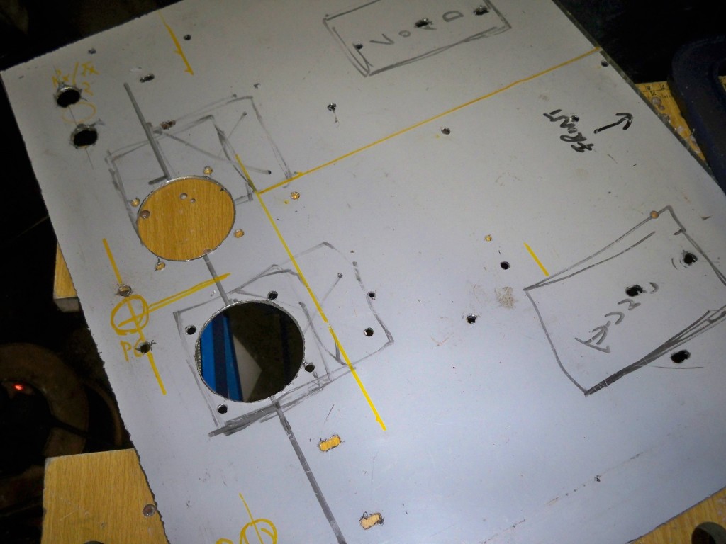
Next up is the RF deck. It’s taken a lot of drilling to get all the parts ready for mounting and I’m sure there will be a few adjustments needed. The two big holes at the bottom are for the valve bases.
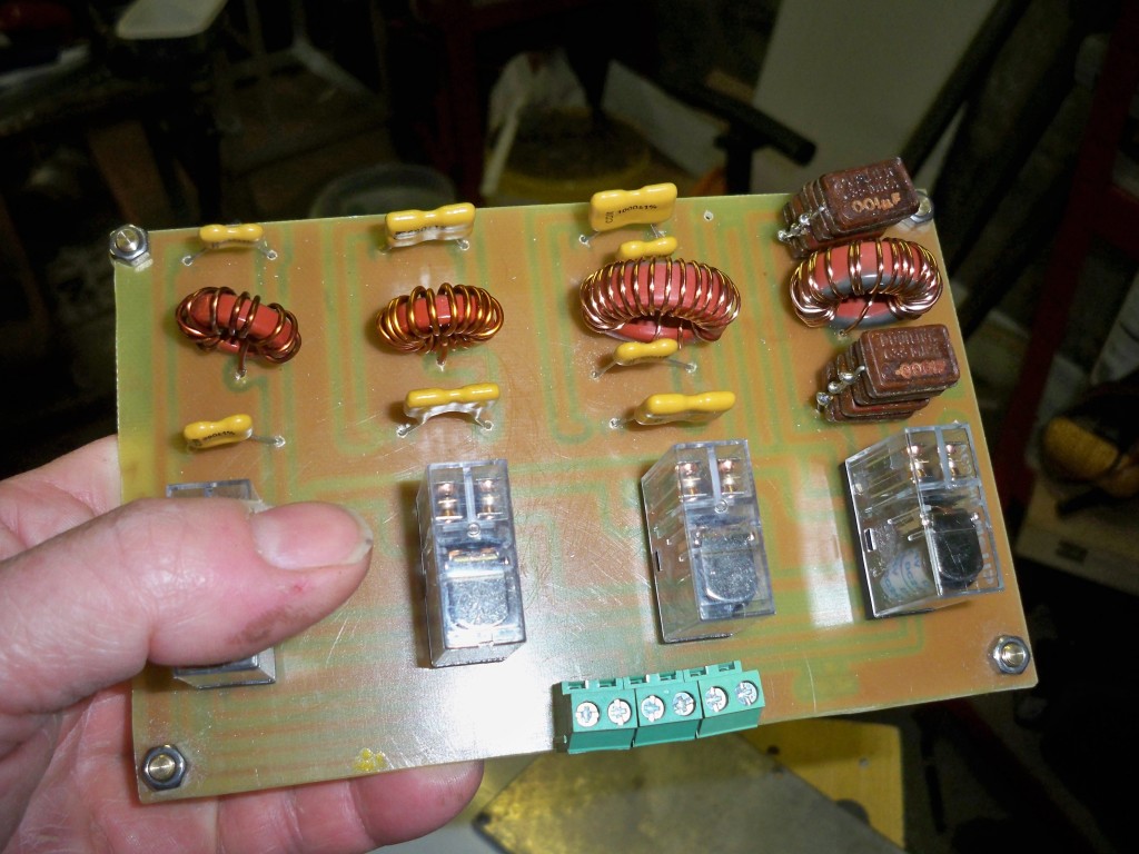
The input pi network was made with a homemade PCB. The plan is to have each one switched in and out with relays.
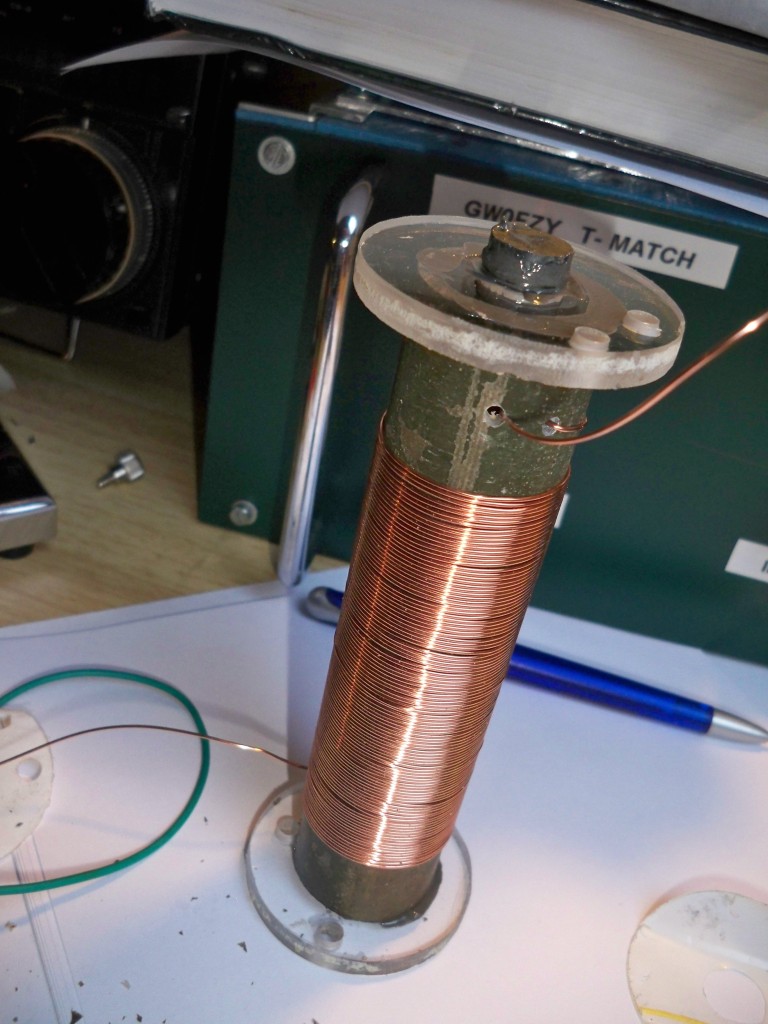
Up next is to wind a few coils. This is the plate choke for the anodes of the valves. The idea is that it allows the HT to get to the anode plates but blocks RF getting into the PSU. I’m using a fibre-glass former of about 1 inch diameter, it was in actual fact an off cut from my vertical antenna. In the centre is an iron powder core to raise the inductance. I’ve checked it with my GDO and it does not have ant resonant frequencies in the HF bands. Total inductance about 900 uH, more than enough.
Now to put all the bits together. You’ll notice from the picture below that I’m using rather unconventional gas filled variable capacitors for the tank circuit. The plate cap is 500pF and the load cap is 1000 pF. These are high voltage capacitors and are rotated using the little motors. My thanks to Paul Bennett for donating them to the project.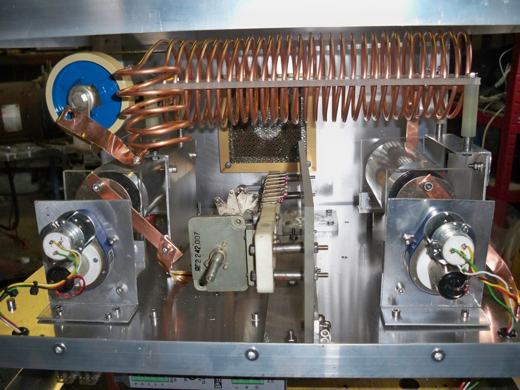
The RF deck is dominated by the massive tank coil. This is a 3 inch diameter coil with about 28 turns of 4mm copper tubing. It has to be quite big in order to tune the 160m band. According to my GDO it will tune down to 1.8 Mhz with the current capacitor combination although I may need come capacitance to increase the Q, I guess we will know when it is tested.
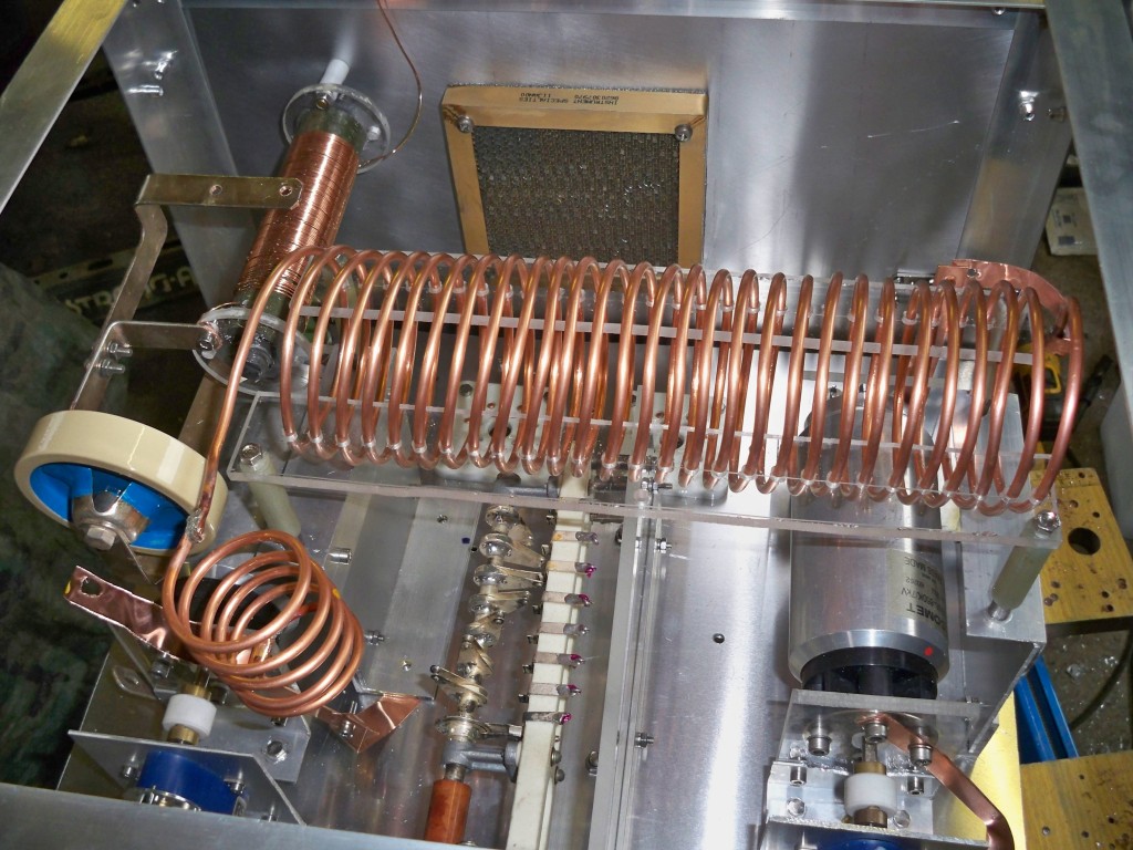 Also in the picture is my 1000pF 10kv isolation doorknob capacitor. Next up is to start the wiring and the taps for the tank coil.
MAY/JUNE 2013
Boy, what a saga this has been!! Putting the amplifier together was fairly straightforward however getting it to work properly was another story. When I first powered it up for it’s first run it seemed to work reasonably well on 160m but not so well on the bands and not at all on 20m. The reasons were twofold: when I first built up the Pi input circuit I used a circuit from the ARRL Amplifier Book which was based on an 8877 triode, I didn’t appreciate that the cathode impedance would be different on a pair of 813’s so this had to be re-done and the components worked out for a cathode Z of about 180 Ohms and not 50 as I had originally done.
The next problem I had was the small switch mode 24v psu that supplied power to the relays and lights blew up after a relay shorted at it’s input contact so this had to re-done with a standard transformer/rectifier circuit. Anyway eventually the input circuitry was eventually sorted and here’s what it looks like before I removed the little psu.
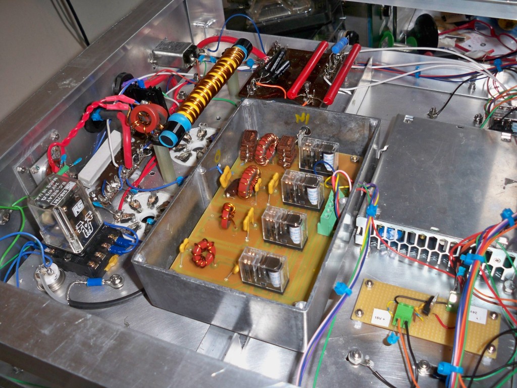 You can see the pi input filters in the middle, towards the rear is the filament choke. There are 2 extra toroids on each filament lead to provide a little more inductance for 160m….my own invention which seems to work!! The 2 chunky resistors are the multiplier for the plate volts meter. Next to them are a couple of non-inductive resistors making up 16 Ohms for the B+ safety resistors. The white ceramic resistor to limit the plate current on standby has been ditched as explained later.
BIASING
This proved a bit of a problem…..I initially used a zener of about 5 or 6 v at 20w for the bias with a big resistor to cut the valves off in standby. This is a fairly standard way of doing it but my 813’s were not happy and went berserk with arcing and God knows what. As I had built up a bias supply and a screen supply in my PSU I decided I would use a variable bias of about -150v that could be adjusted with a 4k pot. I added 400 volts of screen and the valves seemed alot more stable. So the grounded grid plan went out the window.
PLATE CHOKE
I had thought that my problems with 20m could have been due to too much inductance on the plate choke especially with the powdered iron core. In any case as a precaution I made another choke without the core and it seems to work just as well. This was basically a 25mm fibreglass former with about 8 or 9cm of 22 swg wire to an inductance of about 250 uH. I checked for series resonance with my GDO and it all checked out OK.
TANK CIRCUIT
My big coil and caps seemed good for 160m but I could not tune 20m, the reason for this was that the SF4 gas caps had too much residual capacity at their lowest setting. The plate cap was swapped for a 100pF HV air variable. Even then it still would not work on 20m, time to look again at the tank coil. I checked everything with the MFJ analyser for lowest SWR and despite this still no joy. In the end I removed the big tank coil and tried a smaller coil, this time success but now 160m doesn’t work !!@???$!!
Eventually I decided to put back the big tank coil, made a smaller diameter coil for 20m based on the diameter of the coil I used previously which I knew worked. Looking at GM4SEK’s pi-network calculator I entered values for a higher Q which meant more capacity on C2 after further jiggling I got the thing to work, hooray!!
If anyone’s building an amp and a tank circuit for the first time these are my top tips:
1. Use the pi-network calculator and pay attention to the anode impedance resistor when using an MFJ to find the tap points.
2. Use a 3 inch coil for 160, 80 and possibly 40m. A 2 3/4 to 2 1/2 inch coil is needed for 20m and possibly 15m. I did not bother with 10m but that would be even smaller.
3. Be careful with your plate cap, if it has too much residual capacity it will not tune anything higher than 40m. Use fixed HV capacitors to provide more with other lower frequency bands.
4. The MFJ analyser is useful as a guide but can mislead you.
5. Be prepared to add capacitors for more Q especially on 160m. I needed almost 3000pF on my load cap to get it too work!!
After all these problems here’s the finished product:
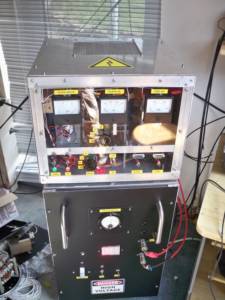 For anyone interested this is the circuit that I used:
And finally a video of the amp in action
http://www.youtube.com/watch?v=dsWZbj2jqC4
