Having been successful with my 813 amplifier I have now decided to take things up a gear and build something even more powerful. The GS35b is a Russian triode that is relatively cheap and easy to get hold of. Originally designed as power triode for UHF Radar applications it has a plate dissipation of about 1500W. Many radio amateurs have used this beast as a power triode in HF linear amplifiers in typical grounded grid configuration. It is similar to the 8877 triode in many respects.
 On our last trip to GB Airspares I picked up this lovely chassis from some sort of aircraft test rig. I have no idea what it was used for but it is about the right size for an amp and had loads of useful bits in it including those fantastic vintage meters. This linear is going to look brilliant and will pack a punch of up to a kilowatt if not more!!

The first job up is to strip down the chassis and get down to the basic framework. The box has a built in shelf that’s just about right for an RF deck. I’ve started to drill a few holes and have built up a cathode compartment for the valve.
 The coil on the side is the tank coil for the 80 and 160m bands. This consists of about 15 turns of 12 AWG Teflon coated wire wound on 5 T300-2 coils (courtesy of Paul Bennett). The total inductance of this coil is 15uH.Here’s another view of the cathode compartment, the hole is for the fan.

The amp is going to be controlled by GM3SEK’s triode board. This used to be available as a kit but I think he got fed up and now just sells the board. This has various safety features built in and will control the biasing.

I’ve ordered all the various components from Farnell and hooray,the box arrived today so I can spend the weekend soldering it all together.
 Next up is to wind the main tank coil. This is made from 1/4″ copper tube and is about 3 inches diameter. This will cover the 15,20 and 40m bands.

I’ve spent most of the evenings during the last week soldering all the parts on to the Triode Board. The manual that you can download is very easy to follow without any ambiguity. Here’s the completed board undergoing calibration. I’m very pleased with it as it works flawlessly!

I’ve spent the last few weekends metal-bashing and finally have completed the cathode compartment and the valve socket. The GS35b is one of the few valves where you have to make up your own base. Here’s the base with the filament and cathode chokes:

Next job is to mount all the boards on the RF deck. I’ve got a multiplier for the plate volts meter which also is used by the triode board to monitor the HT. Also present is the Pi input filter and a couple of PSU boards for the relays etc.

The chassis front panel has been modified to cover up the spaces left by two meters that were not required.

Another view of the top side of the RF deck with the vac caps and band switch:

The wiring has now been completed so before I can switch on I will need to condition the valve. This involves running it for about a day with just the heater on.

The heater uses about 12-13v at just under 3 amps. My AVO shows the current draw is spot-on!
Anyone considering building one of these amps must appreciate that the GS35 requires a significant amount of cooling air that has to forced up from the bottom and through the heatsink. Initially I thought that obtaining a blower that could pump 92 cfm of air would not be an issue and that blowers being blowers would not be that expensive. How wrong that proved to be!! I managed to eventually find a blower but had to get a new one and it cost more than the valve!!!
 The time and method for the “burn-in” process is a bit debatable; some say a few hours with the heater on others recommend leaving the valve on for days then applying some HT and leaving it on for several more hours. I’ve kept mine going for a good 12 hrs and I think that should be OK. After that period I felt confident to connect up the HT and see what happened, luckily no bangs or sparks and so far so good.
I’ve taken a few more pictures of the linear. This shows the valve in situ on top of the cathode box. Note the silicone tube used for the chimney. Most people use PTFE but finding a piece of suitable diameter was impossible. Silicone pipe is good as it is temperature resistant to about 200 degrees C and also has good dielectric properties.
 The tank coil is supported with two fibreglass tubes across the chassis. I think it could be neater but it’ll do.
 Finally, the front panel complete with labels:
 I’m waiting for an RF safety choke to come in the post once it arrives we’ll be able to connect up the linear to the transceiver and see if it all works, ’till next time….
DECEMBER 2013
The linear is almost complete and I have done some initial tests…..it seems to work quite well on 160m and 80m but not very well on 40,20 and 15. I think the tank coil position is not quite right and the interconnecting leads are too long causing too much stray inductance. I think I’ll have to have a major re-build of the tank circuit to try and make things a bit more compact.
Things were looking quite promising but I have had a major disaster with one of the vac-caps. I was testing the rig on 160m and for some reason the safety relays tripped at the point I applied drive to the amp. After close inspection I found a tiny crack in the loading vac-cap which I assume caused a flash-over as a result of the vac-cap losing it’s vacuum.
Luckily I’ve got a spare capacitor but it’s much smaller in value, 200pF instead of 1000pF. I’ll have to swap the plate cap (500pF) over to the load side and put the new 200pf cap into the plate position. In order to achieve the right values of c1 and c2 I will need some padding capacitors which will be switched in and out with vacuum relays by the band switch.
After much re-jigging the amp works well from 160-15m with about 800 watts out from 85watts of drive from my old Icom.
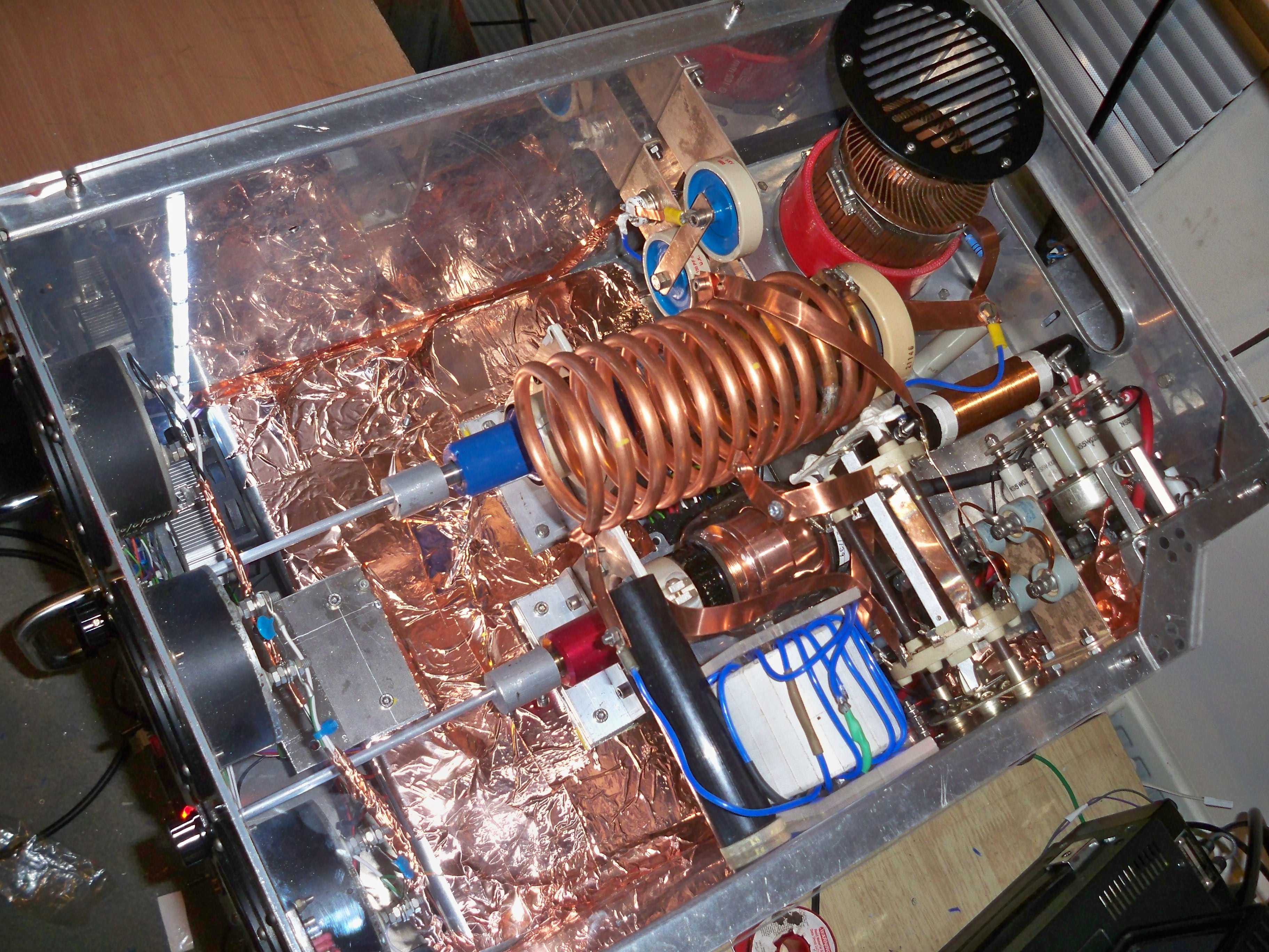
For the final touches I’ve added a perspex cover and copper foil to help screen the RF deck.Here’s a picture of the completed linear:

Here’s a link to Youtube showing a quick tour and demo of the amp:
http://www.youtube.com/watch?v=WoWT6iVcSg0